
Moving Baseline Configuration
Moving Baseline is a dual-antenna technique that derives accurate heading (yaw) directly from two GPS modules mounted on the same vehicle — no magnetometer required. The Orbit Neo Plus supports this natively via its u-blox ZED-F9P chipset and DroneCAN interface.
How It Works
Two Orbit Neo Plus units are mounted on the vehicle. One is designated the Master (Base) and the other the Slave (Rover). The Master sends RTCM correction data to the Slave over the CAN bus. By computing the precise vector between the two antennas, the system derives a highly accurate heading.
Before You Begin
What You Need
- 2× Orbit Neo Plus units
- A CAN bus splitter
- Flight controller running ArduPilot 4.1.5+ or PX4 1.12.3+
- Mission Planner (ArduPilot) or QGroundControl (PX4)
Antenna Placement Rules
Getting the physical mounting right is the most important step. Follow these rules before touching any parameters:
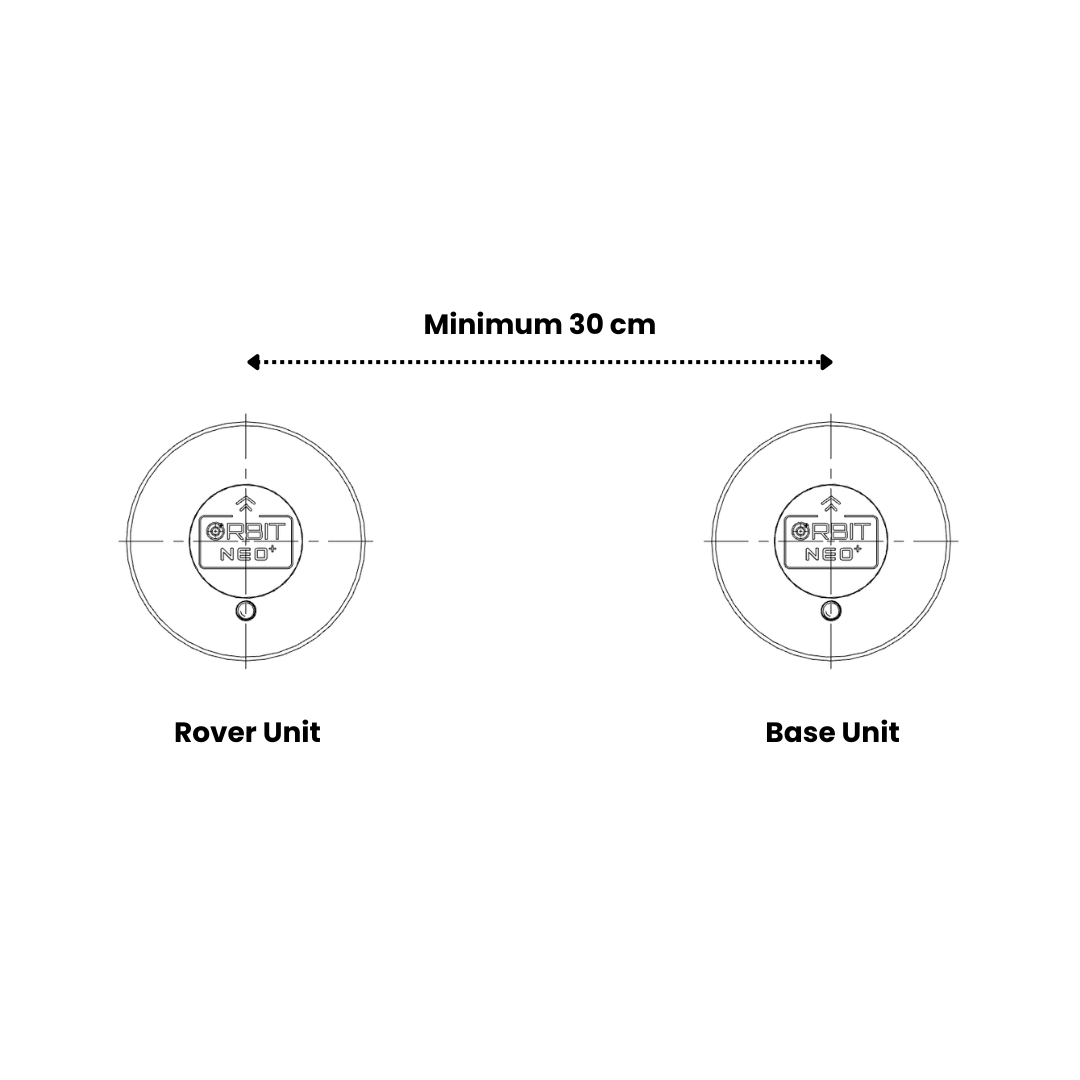
- Minimum separation: 30 cm between the two antennas — more separation means better heading accuracy
- Same height — both antennas must be at the same vertical level on the vehicle
- Same orientation — both units should face the same direction
- Front-to-back alignment — ideally mount Master at the front and Slave at the rear, along the vehicle’s forward (0° yaw) axis
- Same CAN bus — both units must connect to the same CAN bus; use a CAN splitter
Step 1 — Physical Connections
- Connect both Orbit Neo Plus units to the CAN bus using a CAN splitter
- Connect the splitter output to CAN1 (or CAN2) on your flight controller
- Power on the flight controller
Step 2 — Measure Antenna Separation
Before configuring parameters, measure the baseline distance between your two antennas.
Antenna Baseline Distance
Measure the straight-line distance between the two GPS antennas:
- Minimum separation: 30 cm
- Recommended: 50-100 cm for better accuracy
- Maximum: No strict limit, but accuracy improves with longer baselines
Write down this measurement - you’ll verify it during the validation step.
Note: Unlike single-unit dual-antenna systems, you do NOT need to configure individual X/Y/Z offsets. The flight controller automatically calculates the heading vector from the RTK solution between the two units.
Step 3 — Configure Parameters
Choose your firmware below and follow the corresponding steps.
ArduPilot Setup
Open Mission Planner → Config → Full Parameter List.
3a. Enable DroneCAN
| Parameter | Value | Description |
|---|---|---|
CAN_D1_PROTOCOL | 1 | Enable DroneCAN on CAN1 |
CAN_P1_DRIVER | 1 | Enable CAN1 driver |
3b. Set GPS Types
| Parameter | Value | Description |
|---|---|---|
GPS1_TYPE | 22 | DroneCAN Moving Baseline Master (Base) |
GPS2_TYPE | 23 | DroneCAN Moving Baseline Slave (Rover) |
GPS_AUTO_CONFIG | 2 | Auto-configure DroneCAN GPS for Moving Baseline |
GPS_DRV_OPTIONS | 8 | Route RTCM correction data between units via CAN |
3c. Configure EKF for GPS Yaw
| Parameter | Value | Description |
|---|---|---|
AHRS_EKF_TYPE | 3 | Use EKF3 |
EK2_ENABLE | 0 | Disable EKF2 |
EK3_ENABLE | 1 | Enable EKF3 |
EK3_SRC1_YAW | 2 | GPS yaw source — use 3 to allow compass as fallback |
Warning: Do not set
GPS_AUTO_SWITCH = 2(Blend) — it is incompatible with Moving Baseline.
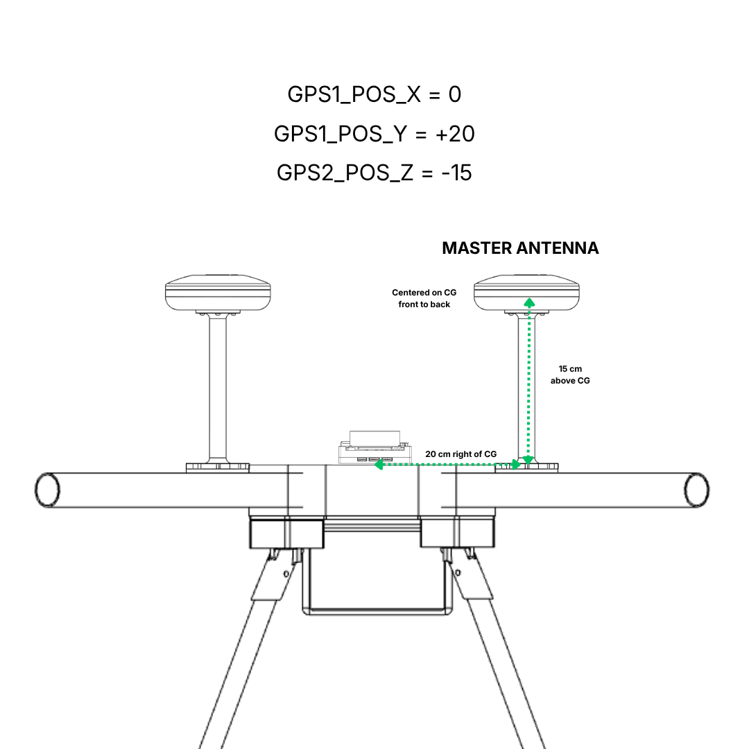
3d. Set GPS Antenna Positions
Measure the position of each GPS antenna relative to the vehicle’s Center of Gravity (CG).
For GPS1 (Master):
| Parameter | Value | Description |
|---|---|---|
GPS1_POS_X | (your measurement) | Master antenna position — X axis (meters) Positive = forward of CG |
GPS1_POS_Y | (your measurement) | Master antenna position — Y axis (meters) Positive = right of CG |
GPS1_POS_Z | (your measurement) | Master antenna position — Z axis (meters) Positive = down from CG |
For GPS2 (Slave):
| Parameter | Value | Description |
|---|---|---|
GPS2_POS_X | (your measurement) | Slave antenna position — X axis (meters) Positive = forward of CG |
GPS2_POS_Y | (your measurement) | Slave antenna position — Y axis (meters) Positive = right of CG |
GPS2_POS_Z | (your measurement) | Slave antenna position — Z axis (meters) Positive = down from CG |
Example: If your Master GPS is mounted 20 cm to the right of CG at the height 15 cm above CG, and Slave is 20 cm to the left at the height 15 cm above CG:
GPS1_POS_X=0.00(30 cm forward)GPS1_POS_Y=0.20(10 cm right)GPS1_POS_Z=-0.15(height 15 cm above CG)GPS2_POS_X=0.00(20 cm behind)GPS2_POS_Y=-0.20(10 cm left)GPS2_POS_Z=-0.15(height 15 cm above CG)
Note: These offsets help the EKF calculate more accurate position and heading. While optional, they’re recommended for best performance.
3e. Write and Reboot
- Click Write Params
- Reboot the flight controller
Note:
GPS1_CAN_NODEIDandGPS2_CAN_NODEIDshow the auto-assigned node IDs after boot. If the wrong unit is being assigned as Master or Slave, useGPS1_CAN_OVRIDEandGPS2_CAN_OVRIDEto swap them.
PX4 Setup
Open QGroundControl → Vehicle Setup → Parameters.
3a. Enable DroneCAN
| Parameter | Value | Description |
|---|---|---|
UAVCAN_ENABLE | 2 | Enable DroneCAN with dynamic node allocation |
Reboot the flight controller so both nodes are detected.
3b. Configure Each Node
In QGroundControl, go to Parameters → DroneCAN and locate the two ZED-F9P nodes by their component IDs.
On the Master (Base) node:
| Parameter | Value | Description |
|---|---|---|
GPS_TYPE | 17 | Moving Baseline Base |
GPS_AUTO_CONFIG | 1 | Enable auto-configuration |
GPS_POS_X | (your measurement) | Master antenna offset from autopilot — X (meters) |
GPS_POS_Y | (your measurement) | Master antenna offset from autopilot — Y (meters) |
GPS_POS_Z | (your measurement) | Master antenna offset from autopilot — Z (meters) |
On the Slave (Rover) node:
| Parameter | Value | Description |
|---|---|---|
GPS_TYPE | 18 | Moving Baseline Rover |
GPS_AUTO_CONFIG | 1 | Enable auto-configuration |
GPS_POS_X | (your measurement) | Slave antenna offset from autopilot — X (meters) |
GPS_POS_Y | (your measurement) | Slave antenna offset from autopilot — Y (meters) |
GPS_POS_Z | (your measurement) | Slave antenna offset from autopilot — Z (meters) |
Coordinate System:
- X-axis: Positive = forward from autopilot
- Y-axis: Positive = right from autopilot
- Z-axis: Positive = down from autopilot
3c. Set Autopilot Parameters
| Parameter | Value | Description |
|---|---|---|
UAVCAN_SUB_GPS_R | 1 | Subscribe to GNSS relative data from Rover |
EKF2_GPS_CTRL | 15 | Enable dual antenna heading fusion |
3d. Write and Reboot
- Save all parameters
- Reboot the flight controller
Step 4 — Verify
Once the flight controller has rebooted and both units have a GNSS fix, run these checks:
Indicator Check
- The RTK Status LED on both Orbit Neo Plus units should be solid, indicating a Fixed RTK lock between them
Heading Check
- Take the vehicle outside to an open area with a clear sky view
- Point the vehicle at a known distant landmark
- Confirm the heading shown in Mission Planner / QGroundControl matches the physical direction
- Slowly rotate the vehicle 360° and verify the heading updates correctly throughout
If the heading appears reversed or offset by 90°, verify which unit is assigned as Master and which is Slave. Use
GPS1_CAN_OVRIDE(ArduPilot) to swap them if needed.
ArduPilot RTK Validation
ArduPilot performs additional checks before accepting the Moving Baseline heading. It verifies that:
- The Slave GPS is in Fix Type 6 (Fixed RTK)
- The measured distance between the two modules is stable
- The height difference between the two modules is consistent with the vehicle’s attitude
It can take a few minutes after obtaining a GNSS fix for all conditions to be met. This is normal.
RTK Correction (Optional)
ArduPilot automatically forwards RTCM correction data received from a ground station or telemetry radio to both GPS units. This allows simultaneous use of a fixed RTK base station alongside Moving Baseline for both centimeter-level position and heading accuracy — no additional configuration is required.